

 English
 Spanish
 Chinese
 Canada
 Mexico
 United Kingdom


The various ultrasonic parameters, or degrees of freedom, available to the process engineer define what the ultimate limits are for the cleaning process. The traditional degrees of freedom available in an ultrasonic cleaning system have included modulation of a single center frequency (sweep), variable duty cycle, and amplitude control at a single frequency. All of these variables allow control of gross, or macroscopic, variables, such as raw power, into the fluid. The latest class of aqueous cleaning technology allows all of the aforementioned parameters, but at multiple center frequencies in a single process tank. Multiple center frequencies allow precise microscopic tuning of the energy in the individual cavitation event. Understanding and optimizing the parameters yields maximal cleaning efficiency with minimal substrate damage. Unlike many popular ultrasonic papers available, the descriptions here are fully referenced and arrived at through sound physical reasoning. This paper intends to undertake the ambitious task of illuminating the various physical effects of these parameters in such a way as to shed as much light and as little heat as possible on this often less than intuitive subject. It is the authors’ desire that this paper is not a final description, but the beginning of a dialog.
The primary physical phenomenon behind the technology of ultrasound is an event known as cavitation. Indeed, any proper treatment of ultrasonic cleaning must begin with a discussion of cavitation. Cavitation is the creation and subsequent collapse of microscopic bubbles within a liquid. These bubbles are formed when a large pressure gradient is introduced into a fluid. During the low-pressure part of a sound wave the fluid is put into tension. When the amplitude of this sound wave exceeds the local tensile strength of the fluid, a void, or cavity, is created in the medium. This cavity grows for the rest of the half cycle of sound. As this bubble grows, both dissolved gasses and fluid vapor diffuse through the walls of the cavity and into the bubble via a process known as rectified diffusion. As the pressure associated with the sound wave begins to go positive, one of two things can happen. The bubble, which grew to a certain size (R0), during the half cycle, can partially collapse. In this case the entrained gasses act as a shock absorber and the bubble may undergo further stable oscillations. The second possibility is that the bubble can suffer complete implosion, an event labeled transient cavitation. Both of these processes re-radiate absorbed energy from the incident acoustic field. It is this re-radiated energy that impinges upon a substrate and does the bulk of the cleaning. Cavitation is one of nature’s most efficient and dramatic amplifiers of energy density currently known. Each bubble collapse is accompanied by the local generation of temperatures on the order of thousands of degrees centigrade and pressures exceeding hundreds of atmospheres. Though recognized for almost a century1, physicists have yet to construct a complete description of this final collapse. Although much of the final implosion event is shrouded in mystery, the bubble dynamics prior to this are quite well understood.2,3,4
Armed with this phenomenological explanation of cavitation we can begin to examine the effects of the various ultrasonic parameters. The relevant questions to be asked are how does the generator impart energy to the transducers, how do the transducers impart that energy to the cavitating cleaning solution and then how is the sonic energy exciting the part being cleaned? It is very important to realize that the cleaning system is composed of both the cleaning solution and the part or parts being cleaned.
Sweeping Frequency
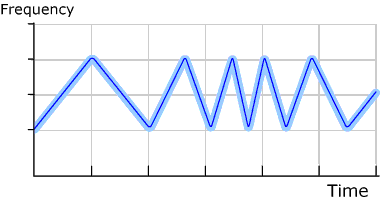
Sweeping frequency, the most primitive type of frequency modulation (FM), has had a major impact on the ultrasonic cleaning industry since the late 1980s. When done correctly, it improves the performance of an ultrasonic cleaner and generally reduces the damage to delicate parts caused by constant frequency ultrasonics. For example, figure 1 shows a graph of frequency versus time for a typical sweeping frequency 104 kHz ultrasonic generator with a four kilohertz bandwidth and a 500 Hz sweep rate.
Introducing a change in the frequency, as a function of time, of an ultrasonic array can effect what happens in a tank in a number of ways. This includes how energy is transferred to the fluid, how efficiently that sound energy is converted into cavitational energy, and how that energy is transferred to the part. All parts absorb energy to a greater or lesser degree and unless extreme precaution is taken in the generation of the FM, this energy can be a significant source of damage. In spite of this fact, it is an effect often neglected.
Sound energy is transferred to a tank via an electromechanical device called a transducer, vibrating at resonance or one of its overtones. Resonance is defined as that frequency at which a mass, in this case a transducer, oscillates with maximum speed amplitude.5 A transducer’s resonant frequency is determined solely by its geometry and composition. An electrical signal, supplied by an ultrasonic generator to the transducers, is converted into an acoustic signal, which is then transmitted into the bath. Natural variations, Δf, exist in the resonant frequency, f, of one transducer compared to another. These random variations occur as a result of variables as mundane as dimensional tolerance build up and transducer to tank bond variations. These resonant frequency variations occur with equal probability on either side of the average frequency of the array, f0=104 kHz in our example, and can be on the order of hundreds of hertz. Thus the resonant frequency distribution of the composite transducer array has an average frequency of f0 with a width of Δf, figure 2. With this in mind, any generator supplying a constant frequency, f0, to a transducer array will be exciting only a fraction of the transducers at their actual resonant frequency. The rest of the transducers will radiate less efficiently, by virtue of being driven off resonance, and portions of the tank will appear acoustically dim. In contrast, if the frequency is swept, say plus or minus 2 kHz, the transducers will all spend an equal amount of time at their resonant frequency. If the transducers are swept quickly (with respect to the typical lifetime of a sound wave propagating through water) the entire array will be excited equally and the sound field in the tank will be very uniform in time. This is a way in which the act of sweeping the frequency of the signal to the transducers results in a more uniform and effective energy transfer into the tank.
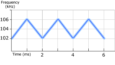
Figure 1
Constant sweeping frequency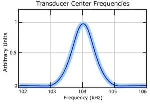
Figure 2
Transducer Center Frequency Distribution
Once a certain amount of ultrasonic energy has been transferred to the fluid medium one must examine how much of that energy is expressed in the form of cavitation. An effective way of representing this is with a mathematical tool known as the acoustic interaction cross-section. Simply, this is the amount of energy subtracted from an acoustic wave by a bubble driven into oscillation. This energy is subsequently re-radiated by the bubble via pulsation or implosion and affects much of the cleaning accomplished by ultrasonics. More precisely the acoustic interaction cross-section is the ratio of the power subtracted from an acoustic wave due to a bubble’s presence to the intensity of the incident beam.1 As its name suggests it has the units of area, i.e. square meters.
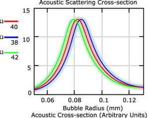
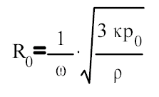
The cross-section is strongly a function of a bubble’s radius, see figure 3, this means that a single frequency picks out it’s favorite sized bubble and pumps energy into it preferentially. The resonant bubble radius, at that frequency, is approximately determined by the following equation:
Where: | κ=polytropic index |
p0=hydrostatic liquid pressure outside the bubble | |
ρ=medium density | |
ω=2πf |
For most aqueous solutions we use κ = 1.3, p0 = 106 dynes/cm2, ρ = 1 gm/cm3. This gives a bubble radius of 0.008 cm at 40 kHz. If we sweep the frequency we are then exciting a range of bubble sizes. For a sweep of plus or minus 2kHz all of the bubbles whose sizes range from 0.0075cm and 0.0083cm are maximally excited. Bubbles whose sizes differ from the resonant size interact less strongly with the incident acoustic field and subsequently absorb less energy for cavitation. This line of thinking would indicate that the larger the sweep bandwidth the better the activity. This is true only to a point. As a transducer is driven off of it’s primary resonance, the efficiency with which it converts electrical energy to mechanical energy decreases. It becomes a game of diminishing returns, a larger sweep bandwidth allows you to excite a larger bubble population but with little energy at the ends of the bandwidth. The optimum transducer is designed with a wide bandwidth resonance allowing a significant transfer of ultrasonic energy into the tank over the entire sweep range.
We have told two thirds of the story thus far. First we examined the way in which sweep effects the amount and uniformity of energy transferred to a fluid medium. Second, we treated the way in which this acoustic energy couples with a bubble distribution in a fluid. Lastly we must discuss those ways in which energy is transferred to a part.
All too often the designers of ultrasonic systems fail to address the question of how a part can be excited in an ultrasonics system. In many cases the knowledge that an ultrasonic system is composed of the sonicated fluid as well as the immersed part is critical. Methods by which energy is transferred to a part must be understood in order to prevent damage modes.
The potential damage modes associated with a fixed frequency sweep rate are eliminated by use of a non-constant sweep rate. This type of frequency modulation (FM) can be accomplished by making the sweep rate random or by changing the sweep rate as a function of time. This type of modulation, known as a “Designer Waveform” is often referred to as sweeping the sweep rate, or dual sweep. An example of a non-constant sweep rate is shown in figure 4.
The main reason for a non-constant sweep rate is to eliminate any single frequency sweep rate from the system because a part being cleaned can be excited into resonance by two times the frequency of the single frequency sweep rate. Many delicate parts will fracture when excited into resonance.
When a typical Langevin type transducer is swept through a bandwidth of frequencies, the output power is not constant for each frequency. Generally, the output power of the generator peaks near the center of the bandwidth. When sweeping up in frequency, a peak pulse of power is put into the tank at the center of the sweep range. When sweeping down in frequency, another peak pulse of power is put into the tank at the center of this sweep range. This process continues producing equally spaced power pulses at a rate equal to two times the sweep rate. This is exactly the prescription required for the high amplitude oscillations associated with a resonant condition. Any time equally spaced periodic bursts of energy are injected into a system at or near it’s resonant frequency, or that of any of its overtones, that system can undergo large amplitude oscillations that can lead to part damage. Introduction of a non-constant sweep rate will vary the spacing between the power pulses. Therefore, there is no fixed frequency at which the power pulses are supplied to the liquid and therefore, no repetitive single frequency to excite the part being cleaned into resonance. Designer Waveforms strive to eliminate all possible damage modes that can be introduced into that system
Power Control
Power control typically comes in two flavors. The first is amplitude control and the second is duty cycle control. Amplitude control changes the integrated power into a fluid by scaling the amplitude of the pressure transmitted into a tank. Duty cycle control changes the power into a tank primarily by changing the period over which the ultrasonics are operated.
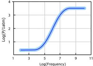
Amplitude control is important in applications where part damage due to peak cavitation intensity is a possibility. The magnitude of a pressure wave is directly effected by amplitude control. Though sound pressure cannot constitute a quantitative measurement of cavitation present in a tank, it is a parameter critical to the strength of cavitation. A certain minimum amount of ultrasonic energy must be present in a tank before a fluid will cavitate. That minimum amount of energy is known as the threshold of cavitation. The threshold of cavitation is a strongly rising function of the frequency of the ultrasonics (figure 5), especially in the high (>100kHz) frequency range.6,7,8 At moderate powers, in a well established cavitation field, the implosion energy is roughly proportional to the square of the difference between the pressure amplitude and the ambient pressure. The reduction of the incident pressure wave’s amplitude tends to reduce the mean value of the overall energy distribution of cavitation events, but it changes it slowly and only over a very narrow range. Because of this, amplitude control alone is an exceptionally rough and unreliable tool by which to eliminate part damage and cavitation erosion.
Duty cycle is a measure of the fraction of the time that a generator’s ultrasonic output is turned on over a given period. At a duty cycle of 50% the ultrasonic output of a generator spends half of the time on and half of the time off. The primary effects of duty cycle are two fold. The first comes from an understanding that the mechanisms of contaminant removal as well as part damage are probabilistic in nature. Duty cycle serves to change the total number of cavitation events that a part is exposed to over a given period. With fewer implosions, and less opportunity to damage, a low duty cycle is kind to soft substrates. As with most variables care must be taken as there is a trade between damage and cleanliness level; less cavitation offers fewer opportunities to remove particles. The second positive effect of duty cycle power control is to reduce what is often referred to as the degas time of a fluid. Time averaged radii of oscillating bubbles tend to increase during sonication through rectified diffusion9. This means that large bubbles (compared to R0) continue to grow to a size where buoyancy forces drive them to the surface of the fluid. The off times introduced by a duty cycle help to give these bubbles an opportunity to travel to the surface. This is an active mechanism by which a bubble population purges itself of large bubbles as well as a pumping action that tends to degas a solution. Via the same mechanism bubble nuclei and small bubbles grow until such time as they are of resonant size and undergo transient collapse. The shattered bubble fragments from this collapse are then new nuclei that further seed the bubble population in a self-sustaining cycle. Members of a bubble population that fall just above the resonant size are allowed to dissolve to a smaller radius during the off times introduced by a duty cycle. These bubbles then have a large interaction cross-section and contribute to the cleaning process. These are two ways in which duty cycle, sometimes called pulse mode ultrasonics, can improve overall performance.
Center Frequency Control
For the purposes of cleaning, the important parameters are the amount of energy released in a cavitation event, and the density of cavitation events. These parameters have a simple relation based upon bubble size. As the bubble radius increases, the energy released at implosion also increases (table 1). With a constant power input into a liquid, this means that the larger the typical bubble, the fewer total number of bubbles there will be per unit of time. An equivalent way of saying this is to say that, at constant input power, the square of the bubble radius is proportional to implosion energy and inversely proportional to bubble density. Armed with this knowledge we can customize cleaning by modifying the bubble radius, and thus the energy in each event, as well as the number density of events. The most effective way of doing this is by changing the frequency of insonation. Low frequencies allow bubbles plenty of time to grow large, while high frequencies give cavitation bubbles only little time to evolve. This is most clearly illustrated in figure 6 where the resonant bubble radius from equation 1 is plotted as a function of frequency. Controlling the energy in each cavitation implosion is important to prevent pitting or craters on the surface of the substrate being cleaned.
| Variable | Symbol | Dependence of Bubble Energy |
| Frequency | ω | ω-2 |
| Pressure Amplitude | P | P5/3 |
| Surface Tension | σ | σ1/3 |
| Density | ρ | ρ-1/2 |
| Bubble Radius | R | R2 |

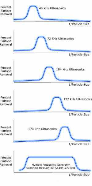
From a cleaning perspective, there is much research on particle removal efficiencies (PRE) at different frequencies. It is observed that low frequency ultrasound has superior PRE for large particles, and that high frequency ultrasound is best suited for submicron particle removal10. Thus, in an optimized single process, one would employ low frequency ultrasonics (few, high energy events) to remove large particles and / or gross contamination, and high frequency ultrasonics (many small low energy events) to remove submicron particles. This constitutes the ideal cleaning process, in which a part can be exposed to relatively low frequency ultrasound, i.e. 40 kHz or 72 kHz, for short amounts of time and then to high frequency ultrasound, i.e. 104 kHz or 170 kHz for long times. Such a process would avoid the damage often associated with low frequency ultrasonics but run the gamut, from large to submicron sized particles, with excellent particle removal efficiency. The most recent technological advances in ultrasonic systems allow such a processing scheme to be realized. There is a new class of liquid cleaning and processing equipment in which there is one transducer array and one generator that produces ultrasound at the primary resonance, or one of a number of overtones, of that transducer array for some given period of time. After this programmed time, the frequency then discontinuously jumps, as specified by the process engineer, to a different overtone of the transducer array for another specified time before discontinuously jumping to a third overtone, and so on.
The improved part cleanliness is best demonstrated by graphs of percent particle removal versus particle size. It has been well established that higher frequencies remove a higher percentage of small particles than do low frequencies.10 There is some minimum size that a frequency removes efficiently, by the same token there is a maximum size particle that any frequency can remove efficiently. If this curve is assumed to be Gaussian in nature, then the graph shown in figure 7 results for a selected center frequency.
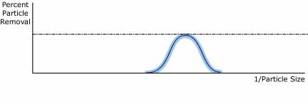
The dotted line in figure 7 represents 100%. The reciprocal of particle size was used on the x-axis to spread out the small particle size numbers.
Consider using the same selected center frequency as was used to generate the graph in figure 7 but increase the exposure time to the ultrasonics. The result is figure 8.
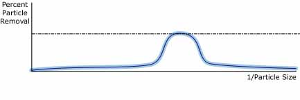
Figure 8 shows that a higher percentage of all particles are removed with longer exposure time with 100% removal at particle sizes within the optimum range for the selected frequency. However, the efficiency of particle removal for particle sizes distant from the optimum size is poor.
Consider the effect on the curve in figure 8 if a higher center frequency is selected. The curve in figure 9 results. The optimum size particle removal is a set of smaller size particles at this higher ultrasonic frequency.
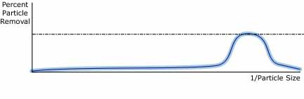
Figure 10 shows the percent particle removal versus the reciprocal of particle size for five different center frequencies. The exposure time at each frequency is chosen to give 100% removal for a range of particle sizes around the optimum value for that frequency. The sixth graph in figure 10 is the sum of the 40 kHz, 72 kHz 104 kHz and 170 kHz graphs. It shows that a wide range of particle sizes can be efficiently removed by scanning through multiple frequencies.
Conclusion
The various ultrasonic parameters available to the user define what the achievable levels of cleanliness and damage minimization are. In this paper we have attempted to highlight and discuss the most dramatic variables involved in an ultrasonic system’s performance. Specifically these variables are sweep, power control and center frequency control.
Modulation of the frequency through sweep effects ultrasonic performance via three main mechanisms. First, sweeping ensures that all of the transducers emit ultrasound evenly and uniformly. Second, by introducing more frequencies into a tank, sweep excites, at resonance, a larger bubble population. This pumps more energy into bubble pulsation and implosion. The third important aspect of sweep is the minimization of damage mechanisms. Smoothly or otherwise varying the sweep frequency, such as dual sweep, eliminates potentially damaging equally spaced power impulses. The equal spacing of these impulsive excitations, especially in transducers characterized by a sharp resonance, threaten to excite delicate parts into damaging sympathetic vibration. With an understanding of the effects of a sweeping frequency the ideal sweep is a fast sweep with a constantly varying rate, over as large a bandwidth as the transducers allow.
Modulation of power into a tank through duty cycle and amplitude control effect ultrasonic activity in different ways. Changing of the peak pressures in a tank through amplitude control changes the average implosion energy about which a bubble population is centered, but smoothly and slowly. Duty cycle serves to quickly modify a bubble population through degassing. Duty cycle also changes the number of cavitation implosions a part is exposed to thus reducing the opportunity for damage. The ideal power control is strongly a function of the part being cleaned as well as the type of contaminant, and must be addressed on a per application basis.
The ability to discretely change the ultrasonic frequency in a tank from a transducer’s primary frequency to any of its overtones, called center frequency control, is perhaps the most versatile and important of the various modifiable ultrasonic parameters available to the engineer. Cavitation implosion energy changes as the inverse of the square of the frequency. As such the only method by which to affect large scale changes in implosion energy is through large discontinuous jumps in frequency, say 72 kHz to 104 kHz. Again the efficacy of cleaning is strongly a function of implosion energy and is different for each application. The ideal ultrasonic device allows center frequency control in a single process for maximal particle removal efficiency across a wide spectrum of particle sizes.
1L. Rayleigh, On the Pressure Developed in a Liquid During the Collapse., Phil Mag 34 (1917) 94-98
2T.G. Leighton, The Acoustic Bubble, Academic Press Inc, San Diego, CA (1994)
3G.L. Gooberman, Ultrasonics Theory and Application, Hart Publishing Company Inc, New York, NY (1969)
4J.R. Blake, et al., Philosophical Transactions of the Royal Soc. Vol. 357 Num. 1751, (1999) 251
5L.E. Kinsler, et al., Fundamentals of Acoustics, John Wiley & Sons, New York, NY (1982)
6J.R. Frederick, Ultrasonic Engineering, J. Wiley, New York, NY (1965)
7S.A. Neduzhii, Soviet Physics-Acoustics, 7 (1961) 221
8R. Esche, Akust. Beih., (1952) AB208
9L.A. Crum. Ultrasonics Vol. 22, (1984) 215-223
10C. Genet, A2C2 Vol. 1 No. 5, Vicon Publishing, (1998) 7-10