By F. John Fuchs and William L. Puskas
Abstract Selection of the proper frequency for an ultrasonic cleaning process and the use of more than one ultrasonic frequency in a single process have been identified as important variables in many ultrasonic cleaning applications. Ultrasonic cleaning effectiveness is enhanced by the use of the proper frequency or multiple frequencies. Recent advancements in ultrasonic hardware offer the user several hardware alternatives when more than one frequency is required in a process. This paper explores the hardware alternatives for producing multiple ultrasonic frequencies and their relative merits. Although three frequencies are used for illustration here, the concepts discussed here may be applied to any number of frequencies.
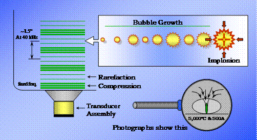
Background Cavitation and Implosions Ultrasonic cleaning relies on the formation and violent collapse of microscopic cavities within a liquid. The cavities, called cavitation bubbles, are formed and grow in liquid under the oscillatory influence of rarefaction (negative pressure) and compression (positive pressure) zones within a traveling sound wave radiating from a vibrating source or transducer. Ultrasonic vibrations are those at frequencies above the limits of human audibility which is around 18,000 cycles per second.
Figure 1 – Cavitation bubbles form and grow in response to the passage of sound waves radiating away from a vibrating source or transducer through a liquid. Once they reach an unstable size, they implode releasing a jet of energy in a shock wave. Cavitation bubbles, once formed, either continue to oscillate for a period of time and then degenerate or ultimately grow to a size that can not be sustained and collapse or “implode” releasing a shock wave which radiates in a “jet” from the point of collapse. It is the latter case that produces what is called “transient” cavitation. Those cavitation bubbles which only oscillate and do not implode produce an effect called “micro-streaming” which may provide micro agitation in their immediate vicinity but do not provide the intense shock wave and “jet” associated with the violent collapse of implosion. Only cavitation bubbles that violently implode produce the intense shock waves that do the work commonly associated exclusively with ultrasonic cleaning.
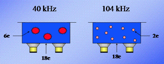
Frequency and Bubble Size Relationship The intensity of the shock wave produced by the implosion of a cavitation bubble is directly related to the size of the cavitation bubble. A larger cavitation bubble will produce a stronger shock wave when it implodes. The size of cavitation bubbles produced by an ultrasonic sound wave is inversely related to frequency – larger cavitation bubbles are produced at a lower frequency. This is because a lower frequency generates wave fronts with a longer time interval between them thereby allowing more time for cavitation bubble growth. The number of cavitation bubbles produced increases with frequency. If ultrasonic input power remains constant, a low frequency will produce fewer cavitation bubble implosions each with higher energy while a higher frequency will produce more cavitation bubble implosions each with lower energy.
Figure 2 – Two ultrasonic cleaning tanks. In this simplified illustration, the tank on the left, operating at 40 kHz, has three cavitation implosion events each with an energy content of 6e for a total of 18e overall. The tank on the right, operating at 104 kHz, has 9 cavitation events each with an energy content of 2e for a total of 18e overall. Although both tanks have the same overall power, the cleaning results will differ because of their different cavitation characteristics. Ultrasonic Cleaning The two basic mechanisms of cleaning are -
- chemical dissolution or emulsification of soluble soils such as oil
- physical displacement of non-soluble soils including particles
In the case of soluble soils, “micro-streaming” resulting from the oscillation of cavitation bubbles that do not implode or the shock waves resulting from the implosion of cavitation bubbles, provide a mixing effect which constantly refreshes the interface between the solvating or emulsifying medium and the soil. This mixing action reduces the time for their thorough interaction to produce a “clean” surface. In the case of non-soluble soils, the pressure resulting from the shock waves produced by the implosion of cavitation bubbles serve to physically displace particles. This displacement breaks the bonds holding the particles to the substrate and moves them far enough away from the substrate to prevent re-attraction or re-attachment. Once free from the substrate, the particles can be flushed away by rinsing.
Delivery of Ultrasonic Energy In order for the energy released by an imploding cavitation bubble to be delivered to the cleaning site, two things are required –
- There must be a continuous liquid in contact with both the source of the sound wave and the surface to be cleaned.
- Cavitation bubbles must form and implode releasing sufficient energy close enough to both the soil and the surface being cleaned to have the desired effect.
The phenomenon of cavitation and implosion resulting from ultrasonic energy can only occur in a liquid but does not necessarily occur in all liquids. Physical properties of liquids including viscosity, surface tension and vapor pressure may affect their ability to support the formation of cavitation bubbles which implode. Many aqueous chemistries are ideal liquids for ultrasonic cleaning. The addition of surface active agents promotes penetration of liquids into even the finest surface detail. When it comes to creating cavitation bubbles in proximity to the surfaces to be cleaned, however, there are some impediments to overcome. Cavitation Bubble Size In order for a cavitation bubble to catastrophically implode, it must first reach an unstable size. If the bubble grows within a confined area too small to allow it to reach an unstable size, it will either not form, or just oscillate and degenerate without ever imploding. Since higher frequencies produce smaller cavitation bubbles, surfaces with small surface details are more likely to be cleaned successfully using higher ultrasonic frequencies.
Figure 3 – Higher ultrasonic frequencies produce smaller cavitation bubbles than lower frequencies. Smaller cavitation bubbles can form in smaller spaces than larger cavitation bubbles.
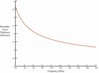
Boundary Layer The “reach” of the ultrasonic effect near a surface is limited by the boundary layer phenomenon. This phenomenon, caused by friction, limits relative motion of a liquid near a surface with which it is in contact. Since the formation of cavitation bubbles requires the presence of a sound wave (motion), there can not be a sound wave where there is not sufficient freedom of motion to allow it to occur. Higher frequency sound waves do not require as much freedom of motion as lower frequency sound waves. Therefore, higher frequency sound waves can penetrate and produce cavitation bubble implosions closer to a surface than can lower frequency sound waves.
Figure 4 – Higher ultrasonic frequencies are effective in closer proximity to the surface being cleaned and can, therefore, remove smaller particles than those at lower frequencies. The boundary layer effect is significant when it comes to removing small particles from a surface. Small particles can “hide” within the relatively thick boundary layer at low ultrasonic frequencies and may not be removed. Increased frequency is required to create cavitation implosions close enough to the smaller particles to remove them. At the same time, however, the smaller cavitation bubbles may not produce sufficient shock wave force to break larger particles free from the surface to which they are attached or attracted. Since most particle populations consist of both larger and smaller particles, the use of more than one ultrasonic frequency is indicated to effect removal of all particles of varying sizes. The above establishes frequency as an important variable in the ultrasonic cleaning process. It also gives support to the notion that the use of multiple frequencies is required to provide total removal of soils from a variety of surfaces.
Multiple-Frequency Ultrasonics – Although ultrasonic systems have been built to operate at a variety of frequencies, each ultrasonic system has historically operated at only a single frequency. The operating frequency is established by the mechanical resonant frequency of the ultrasonic transducer. The transducer, typically an assembly comprised of a series of aluminum blocks or discs and electrically active piezoelectric elements in a “sandwich” configuration, acts as a mechanical transformer and “rings” much like a bell at its resonant frequency when suitably excited by the driving piezoelectric element. Historically, frequencies ranging from 20 to 50kHz were found adequate for most ultrasonic cleaning needs. A few small systems operated at frequencies as high as 90kHz to take advantage of the radial resonance of a piezoelectric element without its being incorporated into the typical multi-layer design described above. The developing need for ultrasonic energy at a variety of frequencies has been met in a number of ways. At first, a number of cleaning baths, each operating at a single frequency, were used in series. Parts to be cleaned were transferred from one bath to the next to take advantage of the effects of all frequencies. This method, although somewhat effective, did not provide an easy means of cycling thorough a succession of frequencies repeatedly and was cumbersome, time consuming and labor intensive to apply. In an ongoing effort to streamline the process, a number of means were devised and evaluated to employ more than one frequency in a single bath, either one at a time in succession or concurrently.
Multiple Frequency Technologies There are two basic ways in which two or more ultrasonic frequencies are introduced into a single ultrasonic cleaning tank in modern day equipment. One is the relatively old method of supplying the different frequencies concurrently or in sequence from a number of transducers or transducer arrays each of which is designed to operate at a single frequency and has its own discreet generator. The second method is relatively new and utilizes a multiple frequency generator which drives universal transducers capable of operating at more than one frequency. The universal transducers produce ultrasound at each of the generator’s operating frequencies. The generator is programmed to supply different sweeping frequencies in succession to the single transducer array.
Figure 5 – In example A, transducers with different operating frequencies are all attached to the same cleaning tank. Each transducer or set of transducers operating at a single frequency is powered by an ultrasonic generator dedicated to that frequency. In example B, all transducers are the same and operate at a variety of frequencies in response to a single ultrasonic generator capable of supplying power at more than one ultrasonic frequency.
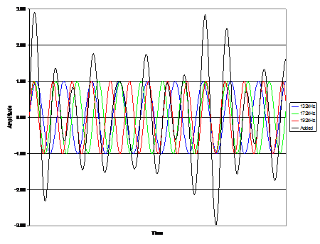
“A” - Multiple, Single-Frequency Transducers In the first case described above, multiple ultrasonic frequencies are produced in a liquid-filled tank by two or more transducers (or transducer arrays) which deliver sound energy into the tank. Different ultrasonic generators drive each of these transducers (or arrays) at its single operating frequency. Typically, all the generators are operated at the same time or with an overlap in the operating times so that two or more frequencies are simultaneously delivered to the tank for at least part of the operating cycle. The chronological history of concurrent multiple ultrasonic frequency equipment starts in 1959 with U.S. Pat. No. 2,891,176 in which Norman Branson teaches three transducer arrays driven by three generators where the operating periods of these generators overlap. In 1974 a tank was designed and built at Branson Cleaning Equipment Company that had an array of 25 kHz transducers on the bottom and a second array of 40 kHz transducers on one side; each of these arrays was simultaneously driven by the appropriate frequency generator. Similar systems were designed and built by others in the 1970's, e.g., Blackstone Ultrasonics, but no useful application was found for the technology. In 1981 U.K. Pat. No. 2,097,890A taught three transducer arrays driven by three generators on different phases of a three-phase line. In the mid 1990's Amerimade Technology sold a system consisting of a tank with angled walls and two arrays of transducers on different walls, each array was driven by a different frequency generator, one sweeping around 71.5 kHz and the other sweeping around 104 kHz. Also at that time, Zenith sold a two-array two-generator system operating at 80 kHz and 120 kHz called "crossfire" because the different frequencies intersected at 90 degrees. Unlike the earlier 25 kHz and 40 kHz systems that found no useful application, the personal computer industry now existed and these Amerimade and Zenith systems were sold in large volume to the hard disk drive industry. In U.S. Pat. No. 5,656,095 Honda, et al. teaches high frequency transducers and low frequency transducers on the tank where the high frequency transducers are normally driven and the low frequency transducers are driven for short periods of time to intermittently destroy the high frequency bubbles. In U.S. Pat. Nos. 5,865,199 and 6,019,852 Pedziwatr et al. teaches two arrays of transducers interspersed on the tank and driven by two different frequency generators. In U.S. Pat. No. 5,909,741 Ferrell teaches two arrays of transducers on different angled walls of a plastic container and driven by different frequency generators. In 2004 Crest Ultrasonics introduced a three-frequency product where the different frequency transducers were spaced in equilateral triangles with each triangle containing the three frequencies and with no frequency next to itself. Systems as described above which have multiple transducers or transducer arrays each dedicated to operation at a single frequency have two primary shortcomings. First, the destructive and constructive interference of the different frequency sound waves results in less transient cavitation compared to sweeping, single frequency systems with the same total power. Second, the two or more different frequency transducer arrays on a given amount of radiating diaphragm surface results in lower power at each frequency. In U.S. Pat. Nos. 5,865,199 and 6,019,852 Pedziwatr et al addressed the shortcoming of interference of different frequency sound waves with an interspersed spacing a distance “D” between adjacent different frequency transducers. “D” was chosen to enable both sets of transducers to operate simultaneously to transmit the different frequencies. However, workable values of “D”, for example, 3.2 inches as suggested by Pedziwatr, result in lower power at each frequency than was achieved in many prior systems. The reason that the destructive and constructive interference of the different frequency sound waves results in less transient cavitation compared to sweeping single frequency systems is because the resultant wave in the liquid has many frequencies that typically exist for one cycle or less. Transient cavitation requires several cycles for the cavitation bubble to oscillate up to the critical energy level required for a transient collapse. The ultrasonic energy in the tank at frequencies where one cycle or less is available generates cavities that grow and then decay, producing micro-streaming, but seldom a transient collapse. It can be expected that in a process where micro-streaming is needed to supply fresh chemistry to a surface, this concurrent multiple ultrasonic frequency technology can be successfully applied.
Figure 6 – The above chart graphically illustrates the effect of simultaneously operating three groups of ultrasonic transducers at different frequencies on a single tank. The traces with an amplitude of 1 unit show the displacement of each group of transducers at the three different frequencies. The black trace with a maximum amplitude of approximately 3 units shows the additive effect achieved when the three individual traces are added together.
“B” – Multiple Frequency Transducers In 1998, Ney Ultrasonics introduced tanks with four frequency transducers driven by individual, discreet generators operating at 40 kHz, 72 kHz, 104 kHz and 170 kHz. This was the first primitive implementation of supplying different sweeping frequencies in succession to an array of transducers that operated at each of the supplied frequencies, i.e., “universal” transducers. This equipment used relays to connect the appropriate frequency generator to the array of “universal” transducers for the period of time required by the process at that frequency. The second frequency required by the process was then supplied to the transducer array by first disconnecting the prior frequency generator and then connecting the generator producing the second sweeping frequency. This frequency switching was done safely by electronic control of the relays and took less than one second of degas time to complete a frequency transition.
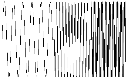
Figure 7 – The above chart graphically illustrates the effect of operating a single array of “universal” transducers at three frequencies sequentially. In this case, amplitude at each frequency remains constant at a level at three times that achievable using three transducer arrays on a single radiating surface. One advantage to the use of a single “universal” transducer array to produce a succession of multiple ultrasonic frequencies is the high power density that can be achieved at each frequency. Each frequency utilizes the total membrane surface to supply that frequency as opposed to the necessity of sharing the available real estate among the various frequencies when using discreet frequency transducers. A second advantage for applications requiring transient cavitation is that many cycles of closely spaced frequencies are available to resonate bubbles up to the energy value needed for transient collapse. It can be expect that a process requiring the removal of small particulate contamination, the removal of spores or the high energies required by sonochemistry will be successfully accomplished by this technology. A third advantage of applying multiple ultrasonic frequencies in succession is realized when cleaning delicate parts. For example, components of a computer hard drive, semiconductors, ferrite parts and optical parts can be excited into resonance and fractured by beat frequencies produced by the interaction of two frequencies, such as exist in concurrent multiple ultrasonic frequency systems. Synchronized sweeping frequencies in succession prevent this damage. However, it is important that the sweeping frequencies have a non-constant sweep rate to eliminate a second source of resonant damage that exists in many modern day sweeping ultrasonic systems. The history of applying multiple ultrasonic frequencies sequentially starts in 1998 with US patent 5,834,871 which taught a universal transducer design and driving it from different frequency generators that were selected by a multiplexer. The above described primitive relay system from Ney Ultrasonics was available that same year. Starting in 1999, follow-on US patents numbered 6,002,195, 6,016,821, 6,181,051 and 6,433,460 disclose improvements on delivering different frequencies in succession to universal transducers and preventing resonant damage to parts being cleaned. In 2000, CAE Ney Ultrasonics replaced the primitive system and sold generators that produced multiple frequencies to drive universal transducers at frequencies selected by a binary code as programmed by a PLC. In 2001 to 2004, US patents 6,313,565; 6,462,461; 6,538,360 and 6,822,372 issued and further protected the multiple ultrasonic frequencies in succession technology and the circuitry required to produce these generators. In 2002, Blackstone~NEY Ultrasonics introduced a seven frequency generator driving universal transducers from 40 kHz to 270 kHz.
Summary and Conclusion The benefit of frequency as a variable in the ultrasonic cleaning process has been identified. Well known effects of higher frequencies are smaller cavitation bubble size, increased numbers of cavitation bubbles and a reduction in the thickness of the boundary layer near a surface. These effects result in more efficient removal of smaller particles. The removal efficiency of larger sized particles, conversely, is decreased as frequency is increased. The use of a succession of multiple frequencies ranging from lower ultrasonic to higher microsonic frequency is most efficient at removing populations of particles that vary widely in size. Single frequency or concurrent multiple frequency alternatives require increased process time and/or higher ultrasonic powers to achieve similar results. Universal transducers developed by Blackstone-NEY Ultrasonics are the only known solution that allows the convenient use of a succession of ultrasonic frequencies in a single ultrasonic tank. The alternative solutions compromise both power and waveform properties to the detriment of process efficacy.


 English
 Spanish
 Chinese
 Canada
 Mexico
 United Kingdom


